• Skip to main content
  • Skip to primary sidebar

Better Bicycles

Science and cyclists making better bikes for transport and leisure

  • Mission
  • BriefBike
    • FAQ
  • About us
  • Contact
  • More
    • News
    • Research
    • Reviews
You are here: Home / Archives for Science / Design

Design

Try our experimental bicycle geometry test rig

24th March 2021 by Jody Muelaner 5 Comments

Test rig to experiment with bicycle geometry

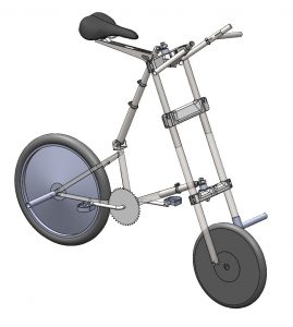
This strange-looking bicycle won’t ever enter production. It’s simply a test rig used to try different riding positions and steering geometries. When designing a folding bike, it can be easier to achieve a compact and convenient fold if you don’t stick to the conventional full-sized bicycle geometry. We will be inviting our product test group to try riding it in different configurations to see how different people feel about different riding positions. If you’d like to give it a try, you can sign-up for the test group.

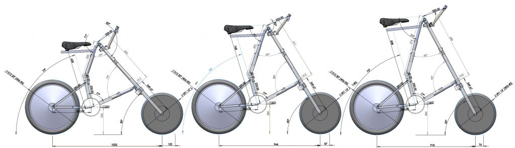
The main frame of this test bike forms a triangle, with each side telescopic. This allows the saddle height, steering angle, and wheelbase to be independently adjusted.

Adjustment in trail - a key bicycle geometry parameter

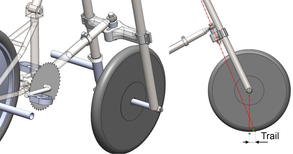
A further adjustment at the lower fork crown will allow the trail to be adjusted, without requiring a change in the steering angle. We’ll also be experimenting with some more unusual bicycle geometry adjustments, such as placing the front and rear wheels offset from the centerline. If our testing shows that this doesn’t have a negative impact on the handling of the bicycle, it could open up some useful options to achieve an even simpler folding action. The bike also uses an adjustable handlebar that will enable a wide range of riding positions and wrist angles.

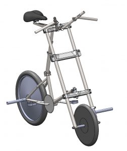
The tubes sticking out from one side of the front wheel and the other side of the rear wheel are to test the effect of uneven luggage loading. Weights will be attached to these tubes to see how they affect the handling, helping us to specify the size of modular luggage attachements.

If you’d like to try riding with the different setups, why not sign-up for the test group and attend a test event in a city near you.

Filed Under: Design

Parametric Model Anthropometric Bicycle

13th November 2020 by Jody Muelaner 1 Comment

Animation showing features of anthropometric human model in parametric bicycle template

A parametric model has been created in SolidWorks in order to facilitate the rapid evaluation of novel bicycle concepts and to fine-tune the ergonomics of more established designs. This article explains the functioning of the model in technical detail.

Some typical uses for this model include:

  • Ergonomic bike fit study
  • Clearances, for example, heals clearing rear chainstays and luggage
  • Visualization of products
  • Aerodynamic studies – although the geometry is overly simplistic for this purpose

Several accurate anthropometric human CAD models are commercially available. However, using these to optimize the fit of a bicycle is not straightforward.  It is especially challenging when considering a range of different riders of different sizes. General bicycle geometry parameters such as seat angle, steering tube angle and wheelbase are already well established. However, when designing an unconventional bicycle this may need to be considered along with clearance for the feet through out their stroke. Handlebar grip position and orientation is particularly important to maintain a neutral position of the wrists.

A Better Bicycle is Coming…

The Better Bicycles team of researchers and engineers aim to make cycling more convenient and enjoyable. Our revolutionary design concept now has UK Government funding to bring it to market. Sign-up to give your feedback on design evaluations or even attend prototype testing sessions.

Join the Better Bicycles User Evaluation Team

The model consists of the following parts:

  • Parametrically defined contact points:
    • Position and dimensions of bottom bracket, cranks and pedals
    • Seat tube angle and seat height
    • Handle bar position and width, grip orientation
  • Steering Characteristics
    • Wheel positions and diameters
    • Steering axis (angle and trail)
  • Anthropometric Human Models in 5th percentile female, 50th percentile male and 95th percentile male:
    • Body consisting of pelvis, abdomen, thorax, clavicles, neck and head. Set to a fixed lean angle.
    • Legs consisting of upper, lower and foot sections. These form kinematic chains with the pedal and crank, so that they are able to move through the pedal stroke.
    • Arms consisting of upper, lower and hands. These form kinematic chains between the clavicles and the handlebar grips allowing them to move as the grip position is adjusted.

Parametrically Defined Contact Points

The contact points are represented by SolidWorks parts, often containing only reference geometry such as points, planes and axes. The parametric representation uses distance and angle mates to position these references within a SolidWorks assembly. For example:

  • Pedal width planes set the centerlines for each foot
  • A crank length part contains three axes: The bottom bracket axis, and two pedal axes. The part has different configurations for standard crank lengths. It is positioned over the origin and the bottom bracket height is set by a distance mate.
  • Pedal thickness parts contain an axis with a plane offset by half the pedal thickness from this axis. The axis is mated to the pedal axis in the crank part and it is orientated relative to the ground by an angle mate.
  • A Dum_Seat part contains a plane representing the seat tube angle and a plane representing the top surface of the saddle. The seat tube plane is mated to pass through the bottom bracket axis and orientated relative to the ground by an angle mate. The saddle surface is set at a distance from the bottom bracket by a distance mate.
  • A Dum_Bar part contains a single axis, running from left to right, to represent the handlebar position. Two distance mates define the reach and height from the bottom bracket.
  • Orientating the handlebars with independent backwards and downwards sweep is difficult with a single part. Intermediate Dum_Grip_Sweep parts are therefore constrained first to define the position and backwards sweep and the actual grips are then constrained relative to these. The six degrees of freedom (DoF) for the Dum_Grip_Sweep parts are constrained by:
    • 2 translations by placing origin on handlebar axis
    • 1 remaining translation by setting origin distance mate from Right plane
    • 2 rotations by setting Top parallel with Top in assembly
    • The remaining angle is backwards sweep, defined parametrically using an angle mate between the Front plane and Front in the assembly
  • The actual Dum_Grip parts are then constrained in a similar way by:
    • 3 translations by placing origin on origin of Dum_Grip_Sweep
    • 2 rotations by setting Front plane parallel with Front in Dum_Grip_Sweep
    • The remaining angle is downwards sweep, defined parametrically using an angle mate between the Top plane and Top in Dum_Grip_Sweep

Its really important to note that angle mates must have a defined direction. Although this may initially be set correctly they are very prone to flipping unexpectedly in SolidWorks. Defining a reference entity for each angle mate will prevent this happening. Reference entities are not created by default when setting up angle mates and this must be done manually, although it is normally just a case of clicking the button to Auto Fill Reference Entity.

Human Model Kinematic Overview

The human model is made up of a number of fixed components and separate kinematic chains.

In total, the model is made up of 19 separate bodies, giving 114 DoF without any joints or other constraints. The bodies are as follows:

  • Hands (x2)
  • Lower Arms (x2)
  • Upper Arms (x2)
  • Clavicles (x2)
  • Head
  • Neck
  • Thorax
  • Abdomen
  • Pelvis
  • Upper Leg (x2)
  • Lower Leg (x2)
  • Foot (x2)

This model of the body has the following basic joints, with the DoF they remove given in parenthesis:

  • Hand to lower arm (Wrist): Spherical (2x 3 DoF)
  • Lower arm to upper arm (Elbow): Revolute (2x 5 DoF)
  • Upper arm to Clavicles (Shoulder): Spherical (2x 3 DoF)
  • Clavicles to thorax (Clavicles): Universal (2x 4 DoF)
  • Head to neck (Neck1): Revolute (5 DoF)
  • Neck to thorax (Neck2): Revolute (5 DoF)
  • Thorax to abdomen (Thoracic): Revolute (5 DoF)
  • Abdomen to pelvis (Lumber): Revolute (5 DoF)
  • Pelvis to upper leg (Hip): Spherical (2x 3 DoF)
  • Upper leg to lower leg (Knee): Revolute (2x 5 DoF)
  • Lower leg to foot (Ankle): Spherical (2x 3 DoF)

This model therefore has 42 DoF without grounding any bodies. There are normally five contact points between a cyclist and a bicycle. These are at the hands, feet and saddle. If it is assumed that each of these fully constrains motion in 6 DoF then there will still be 12 DoF in the model which are as follows:

  • Bend at the four revolute joints along the spine (x4)
  • The position of the shoulders, hunched up or forwards (x4)
  • Rotation of the shoulders, affecting whether the elbows are tucked-in or are out to the sides (x2)
  • Rotation of the legs at the hips, affecting the width between the knees (x2)

The exact kinematic arrangement depends on how the rider’s position is required to be adjusted. The first part of this article therefore details how the model was constructed so that the basic kinematic arrangement could be mapped to anthropometric data. The second part then considers the details of constraining the model to correctly represent different types of motion and adjustments relevant to cycling.

Creating Kinematic Joints from Mates

Although in some cases a more complex arrangement is required, most joints are either spherical or revolute. These can be achieved most efficiently using the following constraints:

  • Spherical: This constrains all three translations and no rotations. Making two spherical surfaces concentric will achieve this although making two points to be coincident may be more robust, I’ve not really worked out if it makes a difference.
  • Revolute: This constrains all three translations and two rotations, leaving a single rotation. It is often achieved using solid geometry by mating two cylindrical faces and two planes which are perpendicular to the axis. However, this is over constrained since both mates constrain the two rotational degrees of freedom. For a perfect kinematic arrangement it is better to start with a spherical joint and then make two planes or faces parallel. Alternatively two axes can be made coincident and then a point made coincident with a plane which is perpendicular to the axis.

Kinematic Chain for Leg and Crank

Each leg normally forms a kinematic chain which also includes a crank and pedal. It is assumed that the hips and the bottom bracket shell form a single grounded link in the kinematic chain. The following ungrounded links must therefore be considered:

  • Upper Leg
  • Lower Leg
  • Foot and pedal
  • Crank

This model implies that the foot is fully constrained to the pedal. These four bodies have 24 DoF and are naturally constrained by the following joints, with the degrees of freedom they remove given in parenthesis:

  • Spherical hip joint (3)
  • Revolute knee joint (5)
  • Spherical ankle joint (3)
  • Revolute pedal axle joint (5)
  • Revolute crank axle joint (5)

This leaves three degrees of freedom:

  • Crank position, this degree of freedom allows the pedaling motion
  • Foot angle with respect to the floor. Some cyclists keep the foot parallel with the floor, some extend the foot slightly at the bottom of the stroke, and some keep the toe pointed slightly downwards throughout the stroke.
  • Rotation of leg about line through the two spherical joints at the knee and the ankle. Assuming the leg is not completely straight, this can be considered as the width of the knee from the central plane.
Simplified view of kinematic chain for cyclists leg and crank
Simplified model of leg-crank kinematic chain with showing the additional constraint on the knee width working correctly (left) and failing when the leg is fully straight (right). This can be prevented by limiting the knee angle so that the leg does not fully lock out.

If setting the knee width proves too unstable for a particular model, there is an alternative way to control the leg rotation. An axis on the upper leg part, passes through the hip joint and points directly forwards, perpendicular to the front plane. If this axis is constrained to be parallel with the central plane of the assembly this will also keep the leg pointing forwards. This method can be more robust but gives less control over the knee position.

Alternative method of constraining outwards knee rotation

A limit mate may also be required to stop the knee joint passing a toggle point and reversing. A range of angles between 2 degrees and 120 degrees is usually sufficient. However, as explained below, a correctly configured model will never get that close to the toggle point and this shouldn’t be necessary.

I implemented the pedal axis revolute joint and constrained the foot angle with a ‘pedal thickness’ part. This part simply contains an axis and a plane ‘Face of Pedal’ offset from the axis by the pedal thickness.

  • The pedal axis is coincident with an axis in the crank part.
  • The Right Plane of the Pedal Thickness part is coincident with a Foot Centerline plane in the assembly
  • The Top of Pedal plane is at a fixed angle with the Top plane in the assembly.

I then fully constrained the Foot and Pedal Thickness parts by aligning their three primary planes.

Kinematic Chain from Hips to Head and Clavicles.

While the kinematic chain for the legs is determined almost entirely by the position of grounded geometry, the upper body position is largely the result of the angular positions of a series of revolute joints. It is possible to fix the angle of rotation for each of these joints in series, starting with the angle of the pelvis on the saddle and continuing through the lumbar and thoracic spine. However, this makes it difficult to control the overall lean angle which is actually of more interest.

The overall lean angle is quite consistent between individuals. However, the extent to which this comes from tilting the hips forward rather than bending the spine varies a great deal. For simplicity it is easiest to set the lean angle and then apportion this in a typical way between the intermediate joints.

The kinematic chain has four bodies:

  • Pelvis
  • Abdomen
  • Thorax with clavicles fully constrained to it
  • A dummy part containing a plane to represent the total lean angle

The 24 DoF of this kinematic chain are reduced by the following joints

  • Revolute pelvis tilt on saddle (5)
  • Revolute lumbar joint (5)
  • Revolute thoracic joint (5)
  • Revolute joint between pelvis and dummy lean plane (5)
  • Clavicle point on dummy lean plane (1)

This leaves three DoF which are constrained as follows:

  • The dummy lean plane is set at an angle from the assembly Top plane
  • A symmetry mate is set so that half of the forward lean comes from pelvis tilt. The Front plane of the pelvis is the plane of symmetry. The seatpost angle and the forward lean planes are symmetric about it.
  • The abdomen is set to be parallel with the dummy lean plane
Constraining the human upper body when cycling

Kinematic Chain from Shoulders to Handlebars

Each arm forms a kinematic chain consisting of the upper arm, lower arm and hand. The fully constrained clavicle can be considered as a grounded link, as can the handlebar. The three ungrounded links have 18 DoF and are naturally constrained by the joints which remove degrees of freedom as given in parenthesis:

  • Spherical shoulder joint (3)
  • Revolute elbow joint (5)
  • Spherical wrist joint (3)
  • Revolute joint where hand grips handlebar (5)
Kinematic chain from shoulders to handlebars

This leaves two degrees of freedom:

  • Rotation of the hand around the handlebar
  • Rotation of the whole arm so that the elbow moves in a circular path about the axis between the shoulder and wrist joints

One DoF can be simply removed by setting the wrist at neutral flexion with it’s top plane parallel with the forearm axis. The remaining DoF can then be removed in various ways:

  • Setting the distance between a point on the elbow joint and the central plane of the whole model. This is generally easier to adjust and maintain to find a solvable position.
  • Rotation of the hand around the handlebar may be directly constrained by setting an angle between planes on the hand and grip. This may be necessary to assess different positions of an adjustable bar if the brake lever position will be fixed on the bar.
  • Setting the wrist to be in neutral deviation or supination/pronation. Although this may be a desirable constraint it is often hard to maintain and it is usually better to use one of the other constraints while monitoring the wrist angles. The handlebar and rider parameters can then be tuned to achieve wrist angles that are reasonably close to neutral.

Another approach is to consider the kinematic chain from the pelvis up, with following bodies:

  • Body. Note that the actual motion of the body is more complex and not a ridged body, as described above. However, for the purposes of determining DoF’s it can be considered a ridged body with a revolute joint for the overall lean.
  • Upper arm
  • Lower arm
  • Hand
  • Grip

This chain therefore has 30 DoF with the following removed by joints:

  • Revolute body lean joint at hip (5)
  • Spherical shoulder joint (3)
  • Revolute elbow joint (5)
  • Spherical wrist joint (3)
  • Revolute joint between hand and handlebar (5)

These joints remove 21 DoF, leaving nine DoF. These can be constrained by choosing nine out of the following 10 parameters:

  • Overall body lean
  • Grip reach
  • Grip Height
  • Grip width
  • Grip back sweep
  • Grip down sweep
  • Grip / brake lever rotation
  • Three wrist angles

If the overall body lean is left unconstrained and the three wrist angles are set to their neutral positions, it is possible to determine the rider position for those neutral angles and the specified grip position. However, in practice this approach is unstable and difficult to achieve.

Positioning the Human Model on the Bike

Mike Veal is a bike fitter with a background in automotive ergonomics. He also wrote the excellent DIY Dynamic Bike Fitting guide. Mike has provided inputs to this work to ensure that the location of the body relative to the contact points, and the movements of the cyclist, are realistic. The following key points were applied:

  • The pelvis was constrained so that the joint was on the plane of the seat post angle.
  • Seat angles of 73° are generally ideal for bike fit with steeper angles used simply to provide clearance for large wheels. The effective angle for a time-trial bike may be 84°.
  • The angle of the line between the hip and shoulder joints is typically between 45° and 55° from the horizontal. 45° to 50° is usual for a road bike and 50° to 55° is typical for a more relaxed upright position. Dutch bikes can be from 65° to 90°. Since the body parts have different lengths this cannot simply be determined by summing the angles at the joints along the spine. A sensor is therefore added to the model to indicate this angle.
  • The angle of people’s feet relative to the floor is quite personal but a typical value is 15°.
  • At the bottom of the pedal stroke the leg is never as straight as it seems. Typically the angle between the upper and lower leg never exceeds 140°. A lot of literature suggests 150° is an ideal angle but this is generally because a static measurement was taken with the foot parallel to the floor. When pedalling and the foot assumes a natural angle, the actual leg angle is lower.

Wrist position is the most challenging area. The three rotations possible at the wrist joint should all be kept as close to neutral as possible but the comfortable ranges of deviation are different for each rotation axis and there is coupling between them. Establishing the neutral position is also not always straightforward.

Typical ranges of motion for the three types of wrist rotation are:

  • Flexion/Extension: This can be assumed to be fixed at exactly the neutral position. In reality, a rider can adjust this independently of their body position by rotating the hands around the axis of the grip.
  • Deviation: Sideways rotation towards the thumb is radial deviation and rotation towards the little finger is ulnar deviation. The neutral position does not mean that a griped bar is perpendicular to the axis of the forearm but rather that the third metacarpal bone is aligned with the forearm axis. One study found that a natural grip results in a mean angle of 65° between the grip axis and the third metacarpal, with the grip sweeping back as though the wrist was in 25° ulnar deviation. However, the standard deviation was 7°, due mostly to variation between individuals, suggesting significant adjustability may be desirable for this aspect of the grip position. Other studies have put this hand/handle angle 
  • Supination/Pronation: Rotation about the forearm axis is known as supination when the thumb is rotating towards the back of the hand and pronation when it is rotating towards the palm.

Conclusions

Setting up an anthropometric model to check the fit of a bicycle can be very time-consuming. A general-purpose parametric template like this means that the job only needs to be done one and can then be rapidly fitted into any bicycle design. This can be useful for ergonomics, checking clearances, aerodynamic simulation, and product visualization.

Animation showing features of anthropometric human model in parametric bicycle template

A Better Bicycle is Coming…

The Better Bicycles team of researchers and engineers aim to make cycling more convenient and enjoyable. Our revolutionary design concept now has UK Government funding to bring it to market. Sign-up to give your feedback on design evaluations or even attend prototype testing sessions.

Join the Better Bicycles User Evaluation Team

Filed Under: Design

Primary Sidebar

Coming soon – the fastest folder?

Folding bike animation

Follow Us

  • Facebook
  • X
  • LinkedIn
  • Instagram
  • YouTube
Privacy & Cookies: This site uses cookies. By continuing to use this website, you agree to their use.

To find out more, including how to control cookies, see here: Cookie Policy

Patented: GB2605862

European patent pending

  • Facebook
  • LinkedIn
  • EDI Policy
  • Privacy Policy